
3.1
Owner's of the Viking Microwave Oven DMOC205SS gave it a score of 3.1 out of 5. Here's how the scores stacked up:
32
DMOC205SS
VMOC205SS
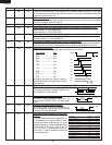
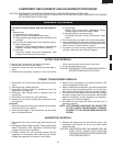
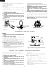
CONTROL PANEL ASSEMBLY AND CONTROL UNIT REMOVAL
To remove the control panel, procedure as follows:
1. Disconnect oven from power supply and remove outer
case.
2. Discharge high voltage capacitor.
3. Disconnect connector CN-A, CN-E and CN-F from the
control unit.
4. Disconnect the wire leads from the relays RY1, RY2 and
RY3.
5. Remove one (1) screw holding the control panel back
plate to the chassis support.
6. Remove two (2) screws holding the bottom edge of the
back plate to the cabinet base.
7. Remove one (1) screw holding the back plate to the oven
cavity flange.
8. Lift up and pull the control panel assembly forward.
Replacement of individual component is as follows;
CONTROL UNIT AND KEY UNIT
1. Disconnect the wire connector from the control unit.
2. Remove the four (4) screws holding the panel frame to
the back plate.
3. Separate the panel frame and back plate.
4. Remove the three (3) screws holding the control unit to
the panel frame.
5. Lift up the control unit and disconnect the key connector
from the control unit.
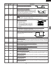
16.Remove the two (2) screws and nuts holding the fan
motor to the fan duct.
17.Now, the fan motor is free.
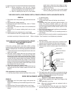
INSTALLATION
1. Install the fan motor to the fan duct with the two (2)
screws and nuts.
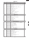
2. Install the fan blade to the fan motor shaft according the
following procedure.
1) Hold the center of the bracket which supports the shaft
of the fan motor on the flat table.
2) Apply the screw lock tight into the hole (for shaft) of the
fan blade.
3) Install the fan blade to the shaft of fan motor by pushing
the fan blade with a small, light weight, ball peen hammer
or rubber mallet.
CAUTION:
* Do not hit the fan blade strongly when installed
because the bracket may be disfigured.
* Make sure that the fan blade rotates smooth after
installation.
* Make sure that the axis of the shaft is not slanted.
3. Reset the fan duct assembly to its place.
4. Install the tabs of fan duct to the rear cabinet and air
guide.
5. Install the magnetron air guide with the one (1) screw.
6. Reinstall the main harness and thermistor harness to
each hole of the fan duct.
7. Reinstall the chassis support to the control panel back
plate, waveguide and rear cabinet with the three (3)
screws.
8. Re-connect the wire leads to the fan motor, referring to
the pictorial diagram.
9. Re-install the fan motor grounding wire to the air guide
(Right) with one (1) screw.
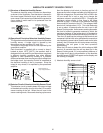
Rear View
Side View
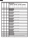
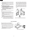
Removal
1. Disconnect oven from power supply and remove outer
case.
2. Discharge high voltage capacitor.
3. Disconnect the white and black wires of the power
supply cord from the noise filter.
4. Remove the one (1) screw holding the earth wire of the
power supply cord to the base cabinet.
5. Remove the power supply cord from the rear cabinet.
Re-install
1. Insert the power supply cord into the rear cabinet.
2. Connect the white and black wires of the power supply
cord into the terminal of noise filter, referring to the
Pictorial Diagram.
3. Re-install the earth wire of the power supply cord to the
base cabinet with the one (1) screw.
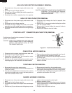
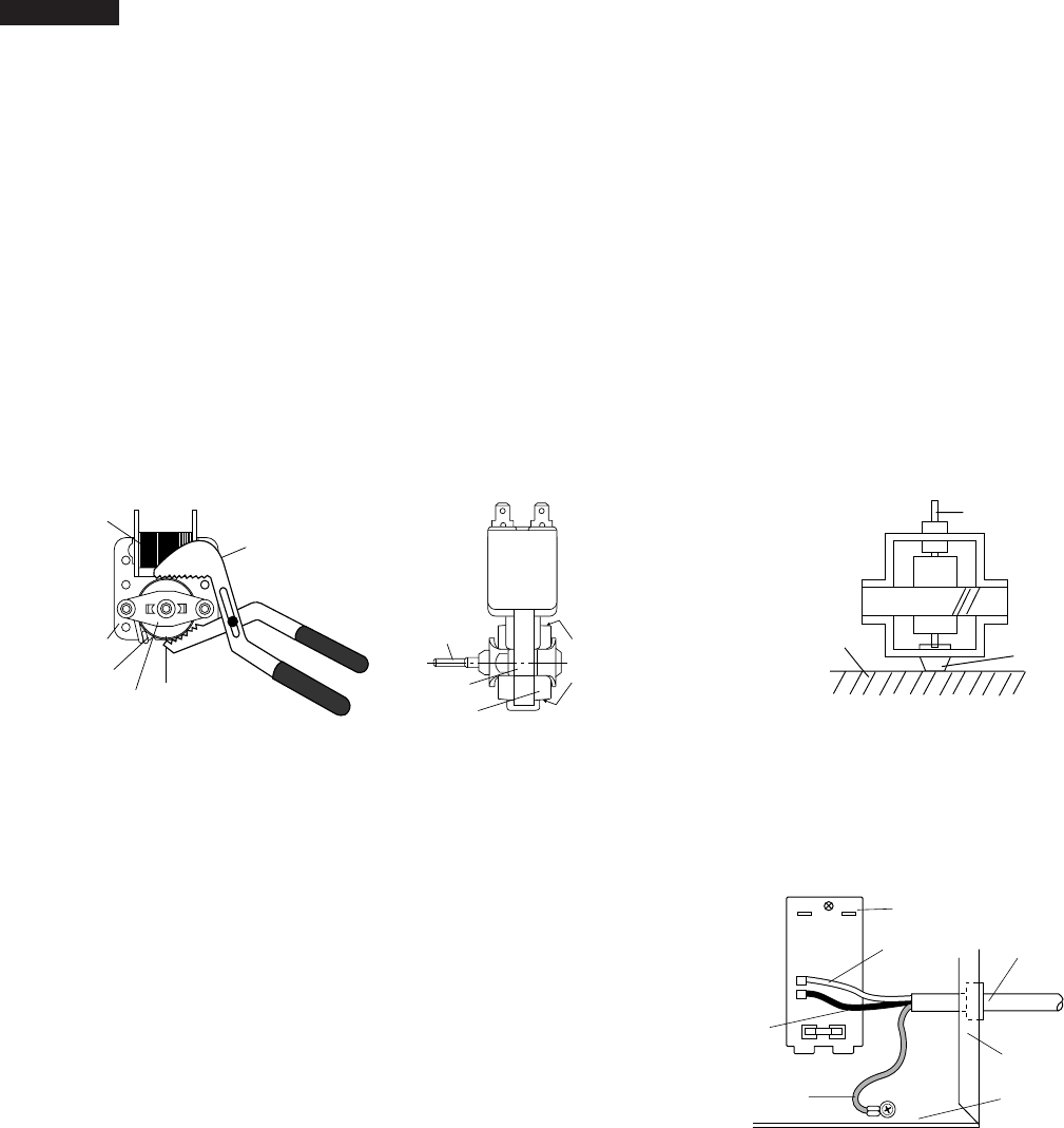
POWER SUPPLY CORD REPLACEMENT
Figure C-3. Power supply cord replacement
Noise filter
Power
supply cord
Rear Cabinet
Base Cabinet
Black wire
White wire
Green wire
N
RED
GRY
H
Gap
Rotor
Bracket
Stator
Groove joint pliers
Coil
Shaft
Axis
Stator
Rotor
These are the positions
that should be pinched
with pliers.
Shaft
Table
Center of
bracket


Find Your Products By Category
Please Login
