
3.1
Owner's of the Viking Microwave Oven DMOC205SS gave it a score of 3.1 out of 5. Here's how the scores stacked up:

29
DMOC205SS
VMOC205SS
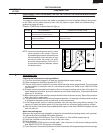
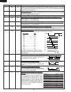
COMPONENT REPLACEMENT AND ADJUSTMENT PROCEDURE
CAUTION: DISCONNECT OVEN FROM POWER SUPPLY BEFORE REMOVING OUTER CASE.
DISCHARGE HIGH VOLTAGE CAPACITOR BEFORE TOUCHING ANY OVEN COMPONENTS OR WIRING
AFTER REMOVING OUTER CASE.
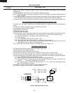
POWER TRANSFORMER REMOVAL
To prevent an electric shock, take the following man-
ners.
1. Before wiring,
1) Disconnect the power supply.
2) Open the door and wedge the door open.
3) Discharge the high voltage capacitor and wait for 60
seconds.
2. Don’t let the wire leads touch to the followiong parts;
1) High voltage parts:
Magnetron, High voltage transformer, High voltage
capacitor and High voltage rectifier assembly.
2) Hot parts:
Convection heater, Oven lamp, Magnetron, High
voltage transformer and Oven cavity.
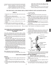
WARNING FOR WIRING
3) Sharp edge:
Bottom plate, Oven cavity, Weveguide flange,
Chassis support and other metallic plate.
4) Movable parts (to prevent a fault)
Fan blade, Fan motor, Switch, Switch lever, Open
button.
3. Do not catch the wire leads in the outer case cabinet.
4. Insert the positive lock connector certainly until its pin
is locked. And make sure that the wire leads should not
come off even if the wire leads is pulled.
5. To prevent an error function, connect the wire leads
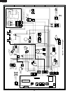
correctly, referring to the Pictorial Diagram.
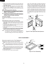
To remove the components, procedure as follows.
1. Disconnect oven from power supply.
2. Remove screws from rear and along the side edge of
case.
3. Slide the entire case back out about 1 inch (3 cm) to free
OUTER CASE REMOVAL
it from retaining clips on the cavity face plate.
4. Lift entire case from the unit.
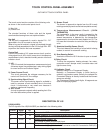
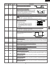
CAUTION: DISCONNECT OVEN FROM POWER SUPPLY
BEFORE REMOVING OUTER CASE.
1. Disconnect oven from power supply and remove outer
case.
2. Discharge high voltage capacitor.
3. Disconnect filament leads of transformer from the
magnetron and capacitor.
4. Disconnect high voltage lead of capacitor from the
transformer.
5. Disconnect wire leads from the transformer.
6. Remove two (2) screws holding the transformer to the
base cabinet.
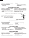
Re-install
1. Rest the transformer on the base cabinet with its primary
terminals toward rear cabinet.
2. Insert the two edges of the transformer into two metal
tabs of the base cabinet.
3. Make sure the transformer is mounted correctly to the
corners underneath those tabs.
4. After re-installing the transformer, secure the transformer
with two screws to the base cabinet, one is with outer
tooth washer and the other is without outer-tooth washer.
5. Re-connect the wire leads (primary and high voltage)
and high voltage lead to the transformer and filament
leads of transformer to the magnetron and capacitor,
referring to the “Pictorial Diagram”.
6. Re-install the outer case and check that the oven is
operating properly.
NOTE HOT (ORANGE) WIRE MUST BE CONNECTED
TO THE POWER TRANSFORMER TERMINAL
NEAREST TO THE TRANSFORMER MOUNTING
SCREW.
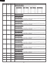
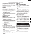
1. Disconnect oven from power supply and remove outer
case.
2. Discharge the high voltage capacitor. Disconnect filament
lead of transformer from magnetron. Disconnect high
voltage wire lead from magnetron.
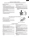
3. Carefully remove four (4) mounting screws hold the
magnetron to waveguide, when removing the screws
holding the magnetron to prevent it from falling.
MAGNETRON REMOVAL
4. Remove the magnetron from the unit with care so the
magnetron tube should not hit by any metal object
around the tube.
CAUTION: WHEN REPLACING THE MAGNETRON, BE
SURE THE R.F. GASKET IS IN PLACE AND
THE MAGNETRON MOUNTING SCREWS ARE
TIGHTENED SECURELY.


Find Your Products By Category
Please Login
