
3.1
Owner's of the Viking Microwave Oven DMOC205SS gave it a score of 3.1 out of 5. Here's how the scores stacked up:


8
DMOC205SS
VMOC205SS
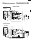
OPERATION
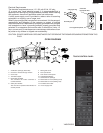
DESCRIPTION OF OPERATING SEQUENCE
The following is a description of component functions
during oven operation.
OFF CONDITION
Closing the door activates the door sensing switch and
secondary interlock switch. (In this condition, the monitor
switch contacts are opened.)
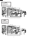
When oven is plugged in, 117 volts A.C. is supplied to the
control unit. (Figure O-1).
1. The display will show "WELCOME, PRESS CLEAR".
To set any program or set the clock, you must first touch
the STOP/CLEAR pad. The display will clear, and " : "
will appear.
NOTE: When the door is opened, the oven lamp comes on.
2. A signal is input to the control unit, energizing the coil of
shut-off relay (RY-4). RY4 contacts close, completing a
circuit to the damper motor. The damper motor now
operates moving the damper to the open position,
thereby closing the contacts of the damper switch
inputs a signal to the control unit. The coil of relay RY-
4 is de-energized, opening its contacts, thereby turning
off the damper motor.
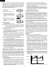
COOKING CONDITION
Program desired cooking time Variable Cooking Control by
touching the NUMBER pads and the power level pad. When
the START pad is touched, the following operations occur:
1. The contacts of relays are closed and components
connected to the relays are turned on as follows.
(For details, refer to Figure O-2)
RELAY CONNECTED COMPONENTS
RY-1 Oven lamp/Turntable motor
RY-2 Power transformer
RY-3 Heating element
RY-4 Damper motor
RY-5 Convevtion motor
RY-6 Fan motor
2. 117 volts A.C. is supplied to the primary winding of the
power transformer and is converted to about 3 volts A.C.
output on the filament winding, and approximately 2360
volts A.C. on the high voltage winding.
3. The filament winding voltage heats the magnetron
filament and the H.V. winding voltage is sent to a voltage
doubler circuit.
4. The microwave energy produced by the magnetron is
channelled through the waveguide into the cavity feed-
box, and then into the cavity where the food is placed to
be cooked.
5. Upon completion of the cooking time, the power
transformer, oven lamp, etc. are turned off, and the
generation of microwave energy is stopped. The oven
will revert to the OFF condition.
6. When the door is opened during a cook cycle, third door
switch, monitor switch, door sensing switch, the
secondary interlock relay and the primary interlock
switch are activated with the following results. The
circuits to the turntable motor, the cooling fan motor, and
the high voltage components are de-energized, the
oven lamp remains on, and the digital read-out displays
the time still remaining in the cook cycle when the door
was opened.
7. The monitor switch is electrically monitoring the operation
of the relay (RY1) and the primary interlock switch and
is mechanically associated with the door so that it will
function in the following sequence.
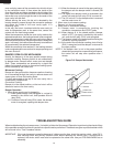
(1) When the door opens from a closed position, the door
sensing switch and the primary interlock switch open
their contacts, and then the monitor switch contacts
close and then the third door switch contacts open.
(2) When the door is closed from the open position, the
monitor switch contacts open and the third door switch
contacts close first, and then the contacts of the primary
interlock switch and the door sensing switch close.
If the relay (RY1) and the primary interlock switch fail with
their contacts closed when the door is opened, the closing
of the monitor switch contacts will form a short circuit
through the monitor fuse, the relay (RY1) and the primary
interlock switch, causing the monitor fuse to blow.
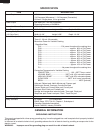
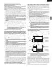
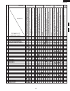
POWER LEVEL P-0 TO P-90 COOKING
When Variable Cooking Power is programmed, the 117
volts A.C. is supplied to the power transformer intermittently
through the contacts of relay (RY-2). RY-2 is operated by
the control unit within an varying time base. Microwave
power operation is as follows:
VARI-MODE ON TIME OFF TIME
Power 10(P-HI) 32 sec. 0 sec.
(100% power)
Power 9(P-90) 30 sec. 2 sec.
(approx. 90% power)
Power 8(P-80) 26 sec. 6 sec.
(approx. 80% power)
Power 7(P-70) 24 sec. 8 sec.
(approx. 70% power)
Power 6(P-60) 22 sec. 10 sec.
(approx. 60% power)
Power 5(P-50) 18 sec. 14 sec.
(approx. 50% power)
Power 4(P-40) 16 sec. 16 sec.
(approx. 40% power)
Power 3(P-30) 12 sec. 20 sec.
(approx. 30% power)
Power 2(P-20) 8 sec. 24 sec.
(approx. 20% power)
Power 1(P-10) 6 sec. 26 sec.
(approx. 10% power)
Power 0(P-0) 0 sec. 32 sec.
(0% power)
Note: The ON/OFF time ratio does not correspond with
the percentage of microwave power, because
approx. 2 seconds are needed for heating of the
magnetron filament.


Find Your Products By Category
Please Login
