
3.1
Owner's of the Viking Microwave Oven DMOC205SS gave it a score of 3.1 out of 5. Here's how the scores stacked up:

28
DMOC205SS
VMOC205SS
SERVICING
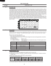
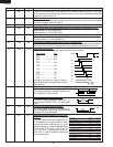
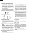
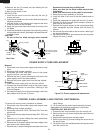
Transistor
2SB910M
Transistor
DTA123ES
KRA101M
KRA223M
KRC243M
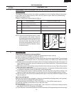
1. Precautions for Handling Electronic Components
This unit uses CMOS LSI in the integral part of the
circuits. When handling these parts, the following
precautions should be strictly followed. CMOS LSI have
extremely high impedance at its input and output
terminals. For this reason, it is easily influenced by the
surrounding high voltage power source, static electricity
charge in clothes, etc, and sometimes it is not fully
protected by the built-in protection circuit.
In order to protect CMOS LSI.
1) When storing and transporting, thoroughly wrap them in
aluminium foil. Also wrap all PW boards containing them
in aluminium foil.
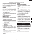
2) When soldering, ground the technician as shown in the
figure and use grounded soldering iron and work table.
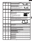
2. Shapes of Electronic Components
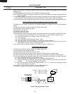
3. Servicing of Touch Control Panel
We describe the procedures to permit servicing of the
touch control panel of the microwave oven and the
precautions you must take when doing so. To perform
the servicing, power to the touch control panel is available
either from the power line of the oven itself or from an
external power source.
(1) Servicing the touch control panel with power supply
of the oven:
CAUTION:
THE HIGH VOLTAGE TRANSFORMER OF THE
MICROWAVE OVEN IS STILL LIVE DURING
SERVICING PRESENTS A HAZARD.
Therefore, when checking the performance of the touch
control panel, put the outer cabinet on the oven to avoid
touching the high voltage transformer, or unplug the
primary terminal (connector) of the high voltage
transformer to turn it off; the end of such connector must
be insulated with an insulating tape. After servicing, be
sure to replace the leads to their original locations.
A. On some models, the power supply cord between the
touch control panel and the oven itself is so short that the
two can't be separated.
For those models, check and repair all the controls
(sensor-related ones included) of the touch control panel
while keeping it connected to the oven.
B. On some models, the power supply cord between the
touch control panel and the oven proper is long enough
that they may be separated from each other. For those
models, therefore, it is possible to check and repair the
controls of the touch control panel while keeping it apart
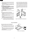
from the oven proper; in this case you must short both
ends of the door sensing switch (on PWB) of the touch
control panel with a jumper, which brings about an
operational state that is equivalent to the oven door
being closed. As for the sensor-related controls of the
touch control panel, checking them is possible if dummy
resistor(s) with resistance equal to that of the controls
are used.
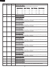
(2) Servicing the touch control panel with power supply
from an external power source:
Disconnect the touch control panel completely from the
oven proper,and short both ends of the door sensing
switch (on PWB) of the touch control panel,which brings
about an operational state that is equivalent to the oven
door being closed. Connect an external power source to
the power input terminal of the touch control panel, then
it is possible to check and repair the controls of the touch
control panel it is also possible to check the sensor-
related controls of the touch control panel by using the
dummy resistor(s).
4. Servicing Tools
Tools required to service the touch control panel
assembly.
1) Soldering iron: 30W
(It is recommended to use a soldering iron with a
grounding terminal.)
2) Oscilloscope: Single beam, frequency range: DC -
10MHz type or more advanced model.
3) Others: Hand tools
5. Other Precautions
1) Before turning on the power source of the control unit,
remove the aluminum foil applied for preventing static
electricity.
2) Connect the connector of the key unit to the control unit
being sure that the lead wires are not twisted.
3) After aluminum foil is removed, be careful that abnormal
voltage due to static electricity etc. is not applied to the
input or output terminals.
4) Attach connectors, electrolytic capacitors, etc. to PWB,
making sure that all connections are tight.
5) Be sure to use specified components where high precision
is required.
approx. 1M ohm
E
C
B
E
C
B


Find Your Products By Category
Please Login
