
3.1
Owner's of the Viking Microwave Oven DMOC205SS gave it a score of 3.1 out of 5. Here's how the scores stacked up:
24
DMOC205SS
VMOC205SS
Pin No. Signal I/O Description
5 AN7 IN Used for initial balancing of the bridge circuit (absolute humidity sensor). This input
is an analog input terminal from the AH sensor circuit, and connected to the A/D
converter built into the LSI.
6 AN6 IN AH sensor input.
This input is an analog input terminal from the AH sensor circuit, and connected to
the A/D converter built into the LSI.
7-9 AN5-AN3 IN Heating constant compensation terminal.
10 AN2 IN Input signal which communicates the door open/close information to LSI.
Door closed; "H" level signal(0V).
Door opened; "L" level signal(-5V).
11 AN1 IN Input signal which communicates the damper open/close information to LSI.
Damper opened; "H" level signal(0V:GND).
Damper closed; "L" level signal(-5V).
12 AN0 IN Temperature measurement input: OVEN THERMISTOR.
By inputting DC voltage corresponding to the temperature detected by the thermistor,
this input is converted into temperature by the A/D converter built into the LSI.
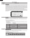
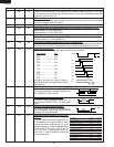
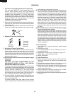
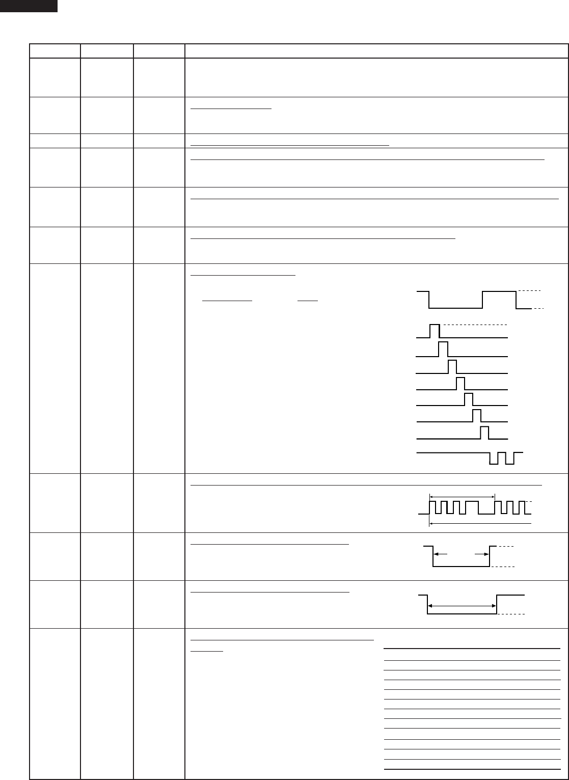
13 P55 OUT Digit selection signal.
The relationship between digit signal and digit are as follows;
Digit signal Digit
P03 .......................... 1st.
P02 ......................... 2nd.
P01 .......................... 3rd.
P00 .......................... 4th.
P37 .......................... 5th.
P36 ......................... 6th.
P35 ......................... 7th.
P55 ......................... 8th.
Normally, one pulse is output in every ß
period, and input to the grid of the Fluores-
cent Display.
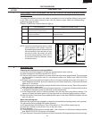
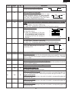
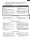
14 P54 OUT Oven lamp and turntable motor driving signal. (Square Waveform : 60Hz)
To turn on and off the shut-off relay(RY1).
The square waveform voltage is delivered to
the relay(RY1) driving circuit.
15 P53 OUT Convection motor driving signal.
To turn on and off shut-off relay(RY5). "L"
level during CONVECTION; "H" level other-
wise.
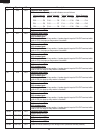
16 P52 OUT Cooling fan motor driving signal.
To turn on and off shut-off relay(RY6). "L"
level during both microwave and convection
cooking; "H" level otherwise.
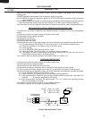
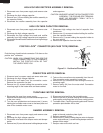
17 P51 OUT Magnetron high-voltage circuit driving
signal.
To turn on and off the cook relay(RY2). In
P-HI operation, the signals holds "L" level
during microwave cooking and "H" level
while not cooking. In other cooking modes
(P-90, P-80, P-70, P-60, P-50, P-40, P-
30, P-20, P-10, P-0) the signal turns to "H"
level and "L" level in repetition according
to the power level.
P03
ß(60Hz)
H
L
GND
VP
P02
P01
P00
P37
P36
P35
P55
During cooking
L
H
16.7 msec.
ON
OFF
During
cooking
L
GND
H.
(Convection)
ON
OFF
During
cooking
L
GND
H.
VARI MODE ON TIME OFF TIME
P-HI (100% power) 32 sec. 0 sec.
P-90 (approx. 90% power) 30 sec. 2 sec.
P-80 (approx. 80% power) 26 sec. 6 sec.
P-70 (approx. 70% power) 24 sec. 8 sec.
P-60 (approx. 60% power) 22 sec. 10 sec.
P-50 (approx. 50% power) 18 sec. 14 sec.
P-40 (approx. 40% power) 16 sec. 16 sec.
P-30 (approx. 30% power) 12 sec. 20 sec.
P-20 (approx. 20% power) 8 sec. 24 sec.
P-10 (approx. 10% power) 6 sec. 26 sec.
P-0 (0% power) 0 sec. 32 sec.


Find Your Products By Category
Please Login
