
3.1
Owner's of the Viking Microwave Oven DMOC205SS gave it a score of 3.1 out of 5. Here's how the scores stacked up:
18
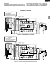
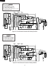
DMOC205SS
VMOC205SS
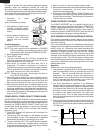
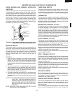
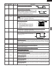
Disconnect connector-E from the control unit. Measure the resistance of the thermistor with an
ohmmeter. Connect the ohmmeter leads to Pin No’s E-3 and E-4.
K THERMISTOR TEST
L DAMPER MOTOR TEST
If the meter does not indicate above resistance, replace the thermistor
Room Temperature Resistance
68
ο
F(20
ο
C) - 86
ο
F(30
ο
C) Approx. 350kΩ - 155KΩ
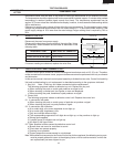
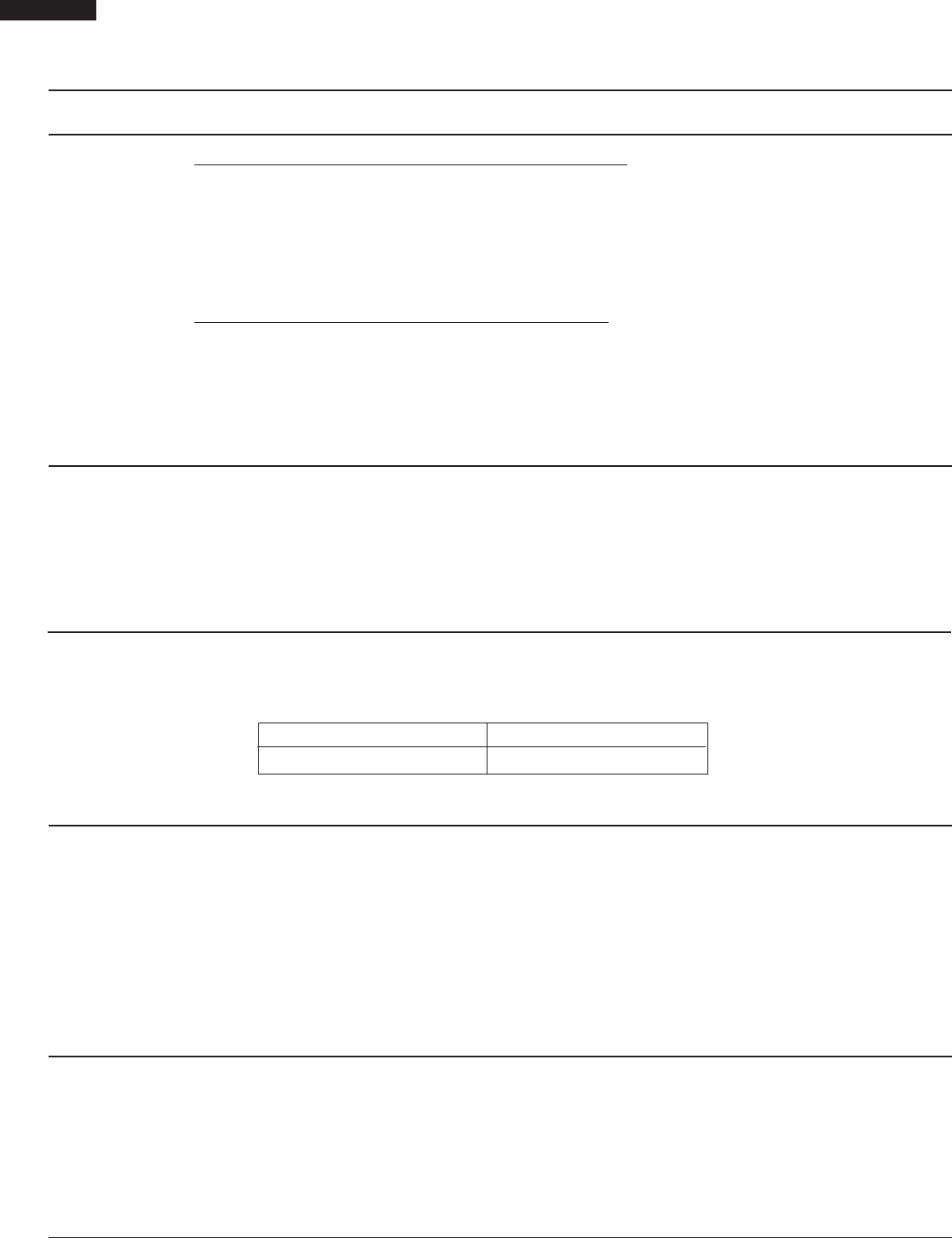
When the power cord is plugged into the wall receptacle and 117 volts A.C. is supplied to the damper
motor, the motor operates until the damper is opened and the damper switch closes. Then the damper
motor stops operation.
If the damper motor does not operate, check for A.C. voltage with a voltmeter at the motor.
1. Disconnect the power cord from the wall receptacle.
2. Disconnect the wire leads of motor and connect the meter leads to the wire leads of main wire
harness.
3. Re-connect the power cord into the wall receptacle.
If 117 volts A.C. is indicated at the wire leads, replace the motor and if 117 volts A.C. is not indicated,
check the wire harness and control unit.
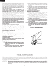
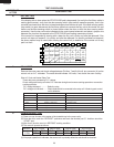
Disconnect the wire leads from the switch terminals and connect ohmmeter leads to the common (COM.)
and normally open (N.O.) terminals of the switch.
1. When switch actuator is pushed by the damper motor cam, the meter should be indicated a closed
circuit.
2. When power cord is plugged into the wall receptacle, the damper motor operates and damper cam
will start to rotate. When the switch actuator is released, the meter should be indicated an open
circuit. If improper operation is indicated, replace the damper switch.
M DAMPER SWITCH TEST
N CHECKING TEMPERATURE IN THE CONVECTION MODE
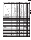
TEST PROCEDURES
PROCEDURE
LETTER
COMPONENT TEST
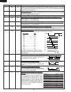
MAGNETRON THERMAL CUT-OUT (on the waveguide)
A continuity check across the thermal cut-out terminals should indicate a closed circuit unless the
temperature of the thermal cut-out reaches approximately 257
ο
F (125
ο
C).
An open thermal cut-out indicates overheating of the magnetron. Check for restricted air flow to the
magnetron through the vent holes of the oven cavity, especially the cooling duct and cooling fan.
CAUTION: IF THE THERMAL CUT-OUT INDICATES OPEN CIRCUIT AT ROOM TEMPERATURE,
REPLACE THE THERMAL CUT-OUT.
CONVECTION CUT-OUT (on side of the heater duct)
A continuity check across the thermal cut-out terminals should indicate a closed circuit unless the
temperature of thermal cut-out reaches 302
ο
F (150
ο
C). The thermal cut-out resets automatically at
approximately 266
ο
F (130
ο
C). If the thermal cut-out has operated under the normal condition,
replace the thermal cut-out. An open thermal cut-out indicates overheating of heater unit, check for
restricted air flow to the heater unit through the vent hole of the oven cavity, especially the heater
duct and convection fan.
J HEATING ELEMENT TEST
Make sure the heating element is fully cooled and test as follows;
a. Disconnect wire leads and measure the resistance with an ohmmeter. On the R x 1 scale, the
resistance between the heating element terminals should be approximately 10.2Ω.
b. Disconnect wire leads and measure the insulation resistance with 500V - 100MΩ insulation
resistance meter. The insulation resistance between heating element terminal and cavity should be
more than 0.5MΩ.
It is difficult to measure the exact temperature in the convection oven. An accurate thermocouple type


Find Your Products By Category
Please Login
