
3.1
Owner's of the Viking Microwave Oven DMOC205SS gave it a score of 3.1 out of 5. Here's how the scores stacked up:
31
DMOC205SS
VMOC205SS
FAN MOTOR REMOVAL
HEATER UNIT ASSEMBLY REMOVAL
(HEATING ELEMENT/CONVECTION FAN/CONVECTION MOTOR/THERMISTOR)
THERMISTOR REMOVAL
1. Disconnect oven from power supply and remove outer
case cabinet.
2. Discharge the high voltage capacitor.
Disconnect wire leads from H.V. capacitor and remove
four (4) screws holding rear cabinet to bottom plate and
three (3) screws holding to heater unit assembly and two
(2) screws holding steam duct to top of oven cavity.
Disconnect wire leads from power supply cord terminals.
3. Disconnect wire leads from thermistor. Remove two (2)
screws from thremistor.
4. Disconnect wire leads from convection motor, thermal
cut-out and heater element.
5. Remove nine (9) screws holding heater duct to the oven
cavity.
6. Remove two (2) screws holding heater duct to base
cabinet. Release two (2) snap bands holding wire harness
to the thermal cover (convection).
7. The heater unit is now free.
1. Disconnect oven from power supply and remove outer
case.
2. Discharge high voltage capacitor.
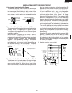
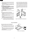
3. Bend the tab of the air guide holding the lamp socket.
4. Lift up the oven lamp socket.
5. Pull the wire leads from the oven lamp socket by
pushing the terminal hole of the oven lamp socket with
the small flat type screw driver.
6. Now, the oven lamp socket is free.
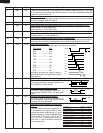
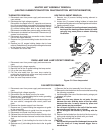
OVEN LAMP AND LAMP SOCKET REMOVAL
Figure C-2. Oven lamp socket
1. Disconnect oven from power supply and remove outer
case.
2. Discharge high voltage capacitor.
3. Disconnect the wire leads from the fan motor.
4. Remove one (1) screw holding the fan motor grounding
wire to the air guide (Right).
5. Remove three (3) screws holding the chassis support to
the rear cabinet, waveguide and control panel back
plate.
6. Remove the chassis support from the oven.
7. Remove one (1) screw holding the magnetron air guide
to the waveguide.
8. Remove the magnetron air guide from the waveguide.
9. Disconnect wire leads from the fan motor.
10. Release the main harness from the hole of the fan duct.
11. Release the thermistor harness from the hole of the fan
duct.
12. Release one (1) tab holding the fan duct to the rear
cabinet.
13. Release one (1) tab holding the fan duct to the air guide
(Right).
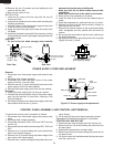
14.Remove the fan duct assembly from the oven.
15.Remove the fan blade from the fan motor shaft according
the following procedure.
1) Hold the edge of the rotor of the fan motor by using a pair
of grove joint pliers.
CAUTION:
* Make sure that any pieces do not enter the gap
between the rotor and the stator of the fan motor
because the rotor is easily shaven by pliers and
metal pieces may be produced.
* Do not touch the pliers to the coil of the fan motor
because the coil may be cut or injured.
* Do not disfigure the bracket by touching with the
pliers.
2) Remove the fan blade from the shaft of the fan motor by
pulling and rotating the fan blade with your hand.
3) Now, the fan blade will be free.
CAUTION:
* Do not use this removed fan blade again because the
hole (for shaft) of it may become bigger than a
standard one.
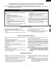
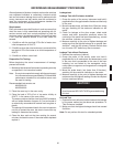
HEATING ELEMENT REMOVAL
1. Remove two (2) screws holding heating element to
heater duct.
2. Loosen two (2) screws holding holders to heater duct
and take heating element out of heating element holders.
3. Heating element is free.
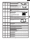
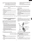
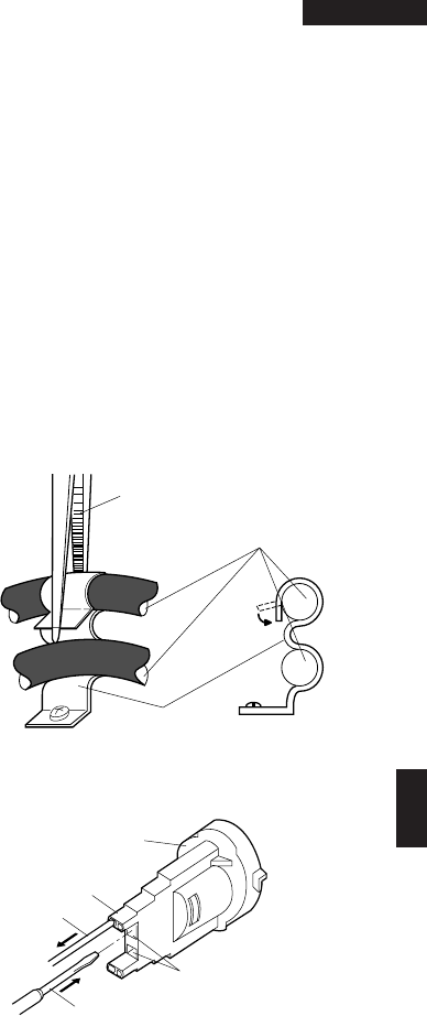
NOTE: After installed the heating element completely,
bent top of the heating element holder to inside
using by long nose pliers as shown following
illustration.
Oven lamp
socket
Terminal
Wire lead
Terminal hole
Flat type small
screw driver
Long nose plier
Heating element
holder
Heating
element


Find Your Products By Category
Please Login
