
3.1
Owner's of the Viking Microwave Oven DMOC205SS gave it a score of 3.1 out of 5. Here's how the scores stacked up:
20
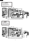
DMOC205SS
VMOC205SS
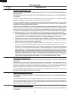
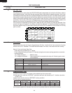
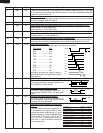
S COMPU DEFROST TEST
(1) Place one cup of water in the center of the turntable tray in the oven cavity.
(2) Close the door, touch the "DEFROST" pad twice and touch the Number pad "5". And then touch the
"START" pad.
(3) After 2 sec. Now the oven is in DEFROST cooking condition.
(4) The oven will operate as follows.
WEIGHT 1ST STAGE 2ND STAGE 3RD STAGE 4TH STAGE
LEVEL TIME LEVEL TIME LEVEL TIME LEVEL TIME
0.5lbs 70% 47sec. 0% 52sec. 50% 32sec. 30% 40sec.
(5) If improper operation is indicated, the control unit is probably defective and should be checked.
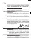
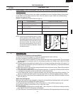
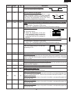
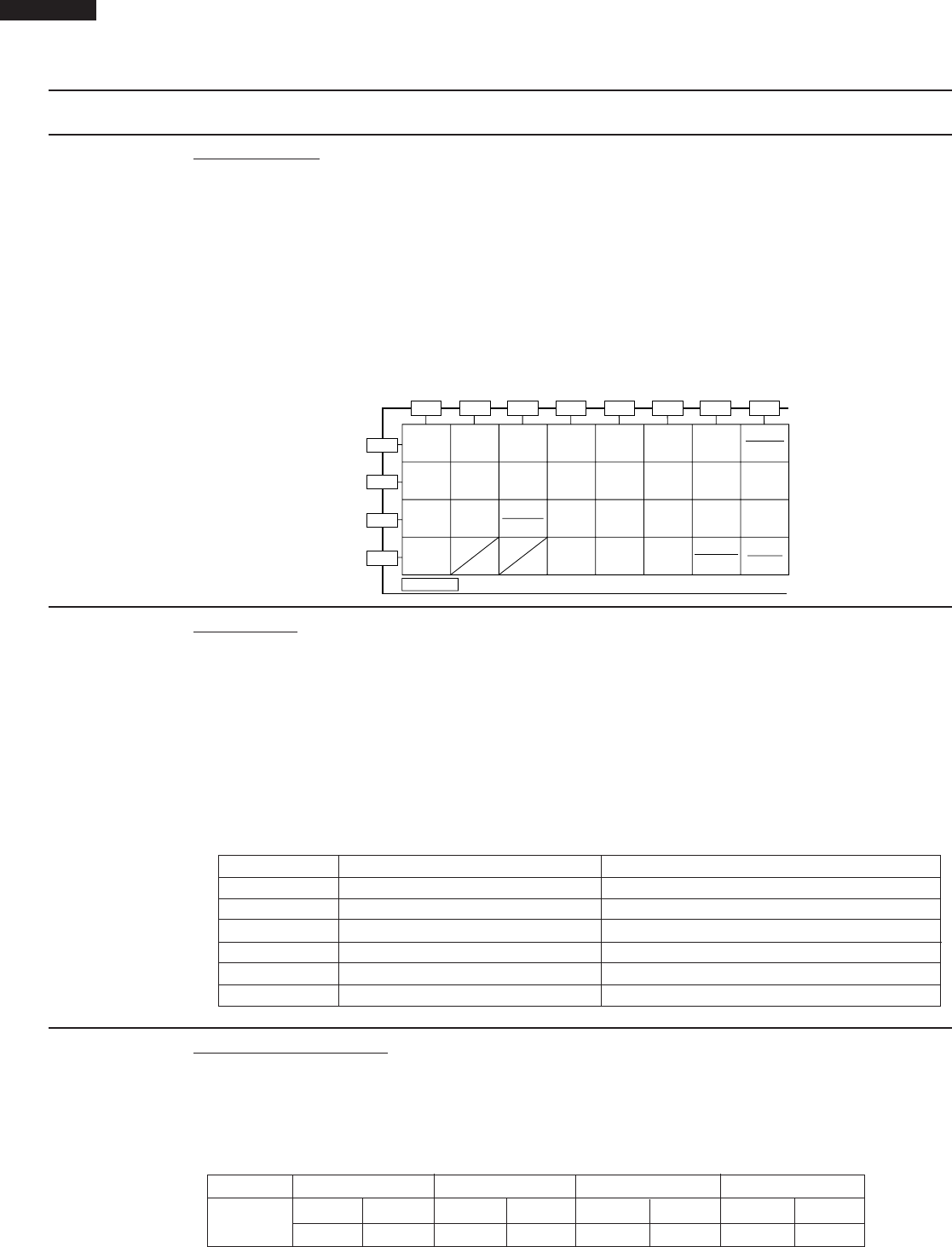
R RELAY TEST
Remove the outer case and check voltage between Pin Nos. 7 and 9 of the 9- pin connector (A) on the
control unit an A.C. voltmeter. The meter should indicate 120 volts, if not check the oven circuitry.
Shut-off, Cook and Heater Relay Test
These relays are operated by D.C. voltage
Check voltage at the relay coil with a D.C. voltmeter during the microwave cooking operation or convection
cooking operation.
DC. voltage indicated ............. Defective relay.
DC. voltage not indicated ........ Check diode which is connected to the relay coil. If diode is good, control
unit is defective.
RELAY SYMBOL OPERATIONAL VOLTAGE CONNECTED COMPONENTS
RY1 Approx. 19.0V D.C. Oven lamp / Turntable motor
RY2(COOK) Approx. 18.0V D.C. Power transformer
RY3(HEATER) Approx. 18.0V D.C. Heating element
RY4 Approx. 19.0V D.C. Damper motor
RY5 Approx. 19.0V D.C. Convection motor
RY6 Approx. 19.0V D.C. Cooling fan motor
TEST PROCEDURES
PROCEDURE
LETTER
COMPONENT TEST
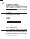
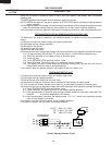
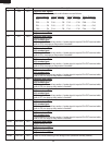
If the display fails to clear when the STOP/CLEAR pad is depressed, first verify the flat ribbon cable is
making good contact, verify that the door sensing switch (stop switch) operates properly; that is the
contacts are closed when the door is closed and open when the door is open. If the door sensing switch
(stop switch) is good, disconnect the flat ribbon cable that connects the key unit to the control unit and
make sure the door sensing switch is closed (either close the door or short the door sensing switch
connecter). Use the key unit matrix indicated on the control panel schematic and place a jumper wire
between the pins that correspond to the STOP/CLEAR pad making momentary contact.
If the control unit responds by clearing with a beep the key unit is faulty and must be replaced. If the
control unit does not respond, it is a faulty and must be replaced. If a specific pad does not respond,
the above method may be used (after clearing the control unit) to determine if the control unit or key
pad is at fault.
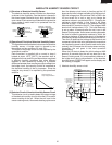
Q KEY UNIT TEST
G 1
G 2
G 3
G 4
G 5 G 6 G 7 G 8 G 9 G10 G11 G12
STOP
CLEAR
REHEAT
LOW MIX
BAKE
SLOW
COOK
HELP
TIMER POWER
LEVEL
CLOCK
ADD-A-
MINUTE
DEFROST
CONVEC
BROIL
CONVEC
ROAST
CONVEC
BAKE
BROIL
SENSOR
COOK
POPCORN
KEY UNIT
350°F 375°F 400°F 425°F 450°F
67890
100°F 150°F 275°F 300°F 325°F
12345
CONVEC
PREHEAT
START
TOUCH ON
HIGH MIX
ROAST


Find Your Products By Category
Please Login
