
3.1
Owner's of the Viking Microwave Oven DMOC205SS gave it a score of 3.1 out of 5. Here's how the scores stacked up:
19
DMOC205SS
VMOC205SS
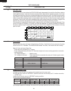
P TOUCH CONTROL PANEL ASSEMBLY TEST
The touch control panel consists of circuits including semiconductors such as LSI, ICs, etc. Therefore,
unlike conventional microwave ovens, proper maintenance cannot be performed with only a voltmeter
and ohmmeter.
In this service manual, the touch control panel assembly is divided into two units, Control Unit and Key
Unit and troubleshooting by unit replacement is described according to the symptoms indicated.
1. Key Unit. Note : Check key unit ribbon connection before replacement.
The following symptoms indicate a defective key unit. Replace the key unit.
a) When touching the pads, a certain pad produces no signal at all.
b) When touching a number pad, two figures or more are displayed.
c) When touching the pads, sometimes a pad produces no signal.
2. Control Unit
The following symptoms indicate a defective control unit. Replace the control unit.
2-1 In connection with pads.
a) When touching the pads, a certain group of pads do not produce a signal.
b) When touching the pads, no pads produce a signal.
2-2 In connection with indicators
a) At a certain digit, all or some segments do not light up.
b) At a certain digit, brightness is low.
c) Only one indicator does not light.
d) The corresponding segments of all digits do not light up; or they continue to light up.
e) Wrong figure appears.
f) A certain group of indicators do not light up.
g) All digits in the figure flicker.
2-3 Other possible troubles caused by defective control unit.
a) Buzzer does not sound or continues to sound.
b) Clock does not operate properly.
c) Cooking is not possible.
d) Proper temperature measurement is not obtained.
Note: When defective components, the Control Unit or Key Unit are replaced, the defective part or parts
must be properly packed for return in the shipping carton, with its cushion material, in which the
new replacement part was shipped to you.
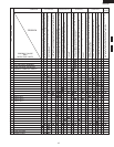
TEST PROCEDURES
PROCEDURE
LETTER
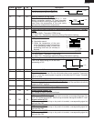
COMPONENT TEST
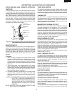
temperature tester must be used. A low priced bi-metal type thermometer is not reliable or accurate.
The temperature should be checked with outer case cabinet installed, approx. 5 minutes after preheat
temperature is reached (audible signal sounds four times). The temperature experienced may be
approx. 30
ο
F more or less than indicated on the display, however, in most cases the food cooking results
will be satisfactory.
Difference in power supply voltage will also affect the oven temperature. The Household power supply
voltage may sometimes become lower than the rated voltage (117 V) and cause under-cooking. If the
power supply voltage is 10% lower than the rated voltage, longer cooking time is required by 10% to
20%.
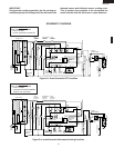
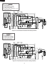
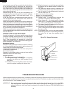
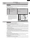
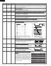
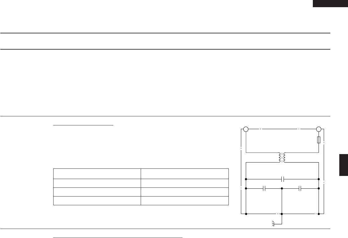
O NOISE FILTER TEST
Disconnect the oven from power supply.
Disconnect the lead wires from the terminal the noise filter. Using
an ohmmeter, check between the terminals as described in the
following table.
MEASURING POINT INDICATION OF OHMMETER
Between N and H Open circuit.
Between terminal N and GRAY Short circuit.
Between terminal H and RED Short circuit.
If incorrect reading are obtained, replace the noise filter.
FUSE 20A
NOISE FILTER
NOISE SUPPRESSION COIL
LINE CROSS CAPACITOR
0.22µF / AC 250V
LINE BYPASS
CAPACITOR
0.0033µF / AC 125V
LINE BYPASS
CAPACITOR
0.0033µF / AC 125V
H
REDGRY
N


Find Your Products By Category
Please Login
