
0
Owner's of the First Alert Weather Radio Public Alert Radio gave it a score of 0 out of 5. Here's how the scores stacked up:
9
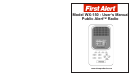
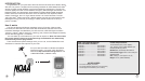
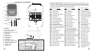
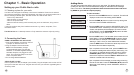
1. Speaker
2. LCD Display – Displays time and alert messages. Also used to display different options when
programming.
3. LED Indicator Lights - “Warning” (Red), “Watch” (Orange), “Advisory ” (Yellow), Power
(Green)
4. Alarm ON/OFF- Press to turn Alarm1 and Alarm 2 off and on.
5. Listen - Press to listen to NOAA weather broadcast
6. Snooze Button - Silences wake-up alarm for a period of 9 minutes.
7. Save - Press to exit and save changes in programmable menus.
8. Menu - Press and hold to enter programmable menus
9. PREV(ious) Button – Use to scroll back through previous menu options while programming.
10. Vol Down - Use to turn volume down and to scroll down through menu lists
11. NEXT Button – Use to scroll forward through menu options while programming.
12. Vol Up - Use to turn volume up and to scroll up through menu lists
13. 18” Integrated Telescopic Antenna – Fully extend the antenna and orient it for best reception.
14. Hang holes - for wall mounting
15. Battery Selection Switch – Select “Alkaline” or “Charge” according to back-up battery type. See
battery installation instructions on page 11 for diagram.
16. Polarity markings - indicates proper + and - alignment of battery.
17. DC Power Jack – Connect AC Adapter or 12V DC from car cigarette adapter (not included)
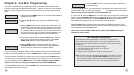
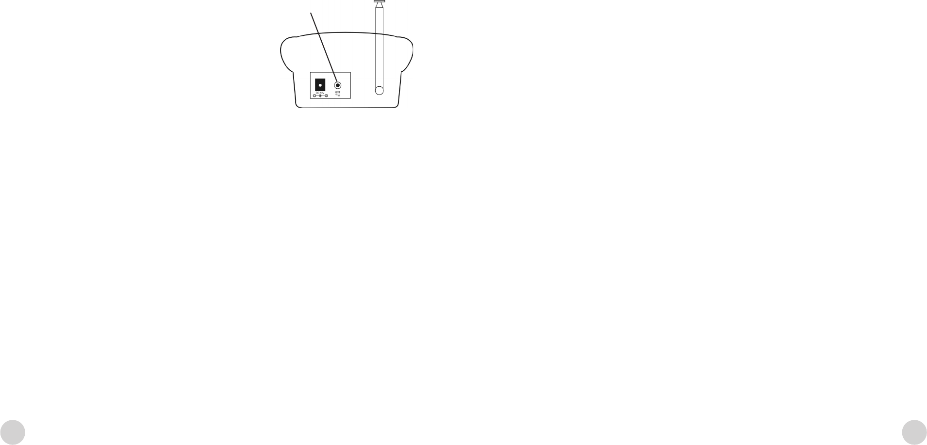
18. Remote Alert (3.5 mm Jack) – Provides contact closure to activate external devices.
Description of controls and functions
24
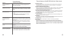
Handicapped Accessories - Appendix B
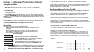
The WX-150 Public Alert radio is equipped to connect a variety of special needs
accessory devices including strobe lights, pillow vibration modules and remote sirens.
Once connected, these devices will automatically be activated when the radio
receives an advisory, watch or warning for the duration of the radio siren or until you
press the Radio OFF button.
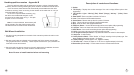
To connect a special needs accessory, plug
the device into the Remote Alert jack on the
rear panel of the radio shown in Fig. 1. This jack
requires a 3.5 mm connector.
Note: If an alert is blocked, the accessory will
not be activated. The Alert Volume switch does
not affect devices connected to the remote alert
Wall Mount Installation
1. Use the mounting template from the back of this manual to position the radio on the
desired wall.
2. Drill two screw holes as indicated on the template and x the screws onto the wall,
using drywall anchors if necessary. Leave a space of about 3mm (1/8”) between the
head of the screw and the wall.
4. Hang the radio onto the two screws on the wall, make sure the installation is secure.
Connect the AC adapter to a power outlet to activate the radio.
Note: Be sure to install batteries before wall mounting


Find Your Products By Category
Please Login
