
0
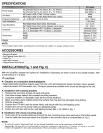
Owner's of the Alpine Car Stereo System Alpine Electronics Car Stereo System gave it a score of 0 out of 5. Here's how the scores stacked up:
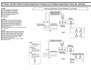

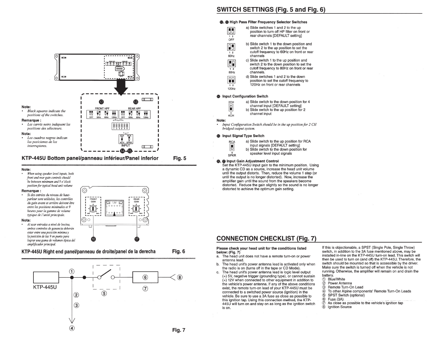
Note:
B
la
ck squar
es
indicate
th
e
positio
ns
of
th
e switch
es.
Remarque:
Les c
arr
es noirs indiquent les
positions des se/ecteurs.
Nota:
Los cuadros n
eg
ros indican
l
as
posiciones
de
los
i
nt
errupt ores.
,
______
_
I
I
48
•
or:::::JD
I
I
I
I
I
I
I
~ ~
I .
~
I
·~~P~'r
or:::::JD
\--------·~-----
KTP-445U Bottom panel/panneau inferieur/Panel inferior
Note:
Wh
en
usin
g spea
ke
r l
eve
l
input
s,
b
oth
fro
nt
and
rear
gain c
on
t
rol
s s
houl
d
be be
tw
ee
n mini
mum
an
d 9 o'
cl
o
ck
po
s
iti
on f
or
typi
cal
head
un
it
volum
e
Remarque:
Si
de
s
entr
ees
du
niveau
de
haut-
parleur
sont
uti/i
sees
, /
es
co
n
tr
ol
es
du
g
ain
avant
et
arri
ere do
iv
e
nt
et
re
e
ntr
e l
es
po
s
itions
min
i
mal
es
et 9
he
ur
es
pour Ia
gamm
e de
vol
um
e
typ
iqu
e de /'
unit
e
prin
ci
pal
e.
Nota:
AI
usa
r e
ntrad
as
a
niv
el
de
boci
na
,
am
bos
co
ntrol
es
de g
anancia
debe
rim
es
tar
entr
e
una
pos
i
ciO
n
minima
y
Ia
po
sic
ion
de l
as
9 en
punto
par
a
/og
rar
un
a g
ama
de
volum
en
ti
p
ic
a d
el
am
p
lifi
c
ad
or
principal.
r-----,
r-----,
1 FR
ON
T 1
1
GAIN
1
h0-
l
~~
r
~
:
=:
lWJ
l
~
l
r
~
KTP-445U
Right
end
paneVpanneau
de
droite/panel
de
Ia
derecha
I
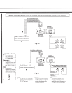
Fig.S
Fig.6
~®
KTP-445U
®
@
®
- I
(J)
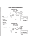
Fig. 7
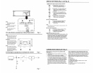
SWITCH SETTINGS (Fig. 5 and Fig. 6)
e.
e High Pass Filter Frequency Selector Switches
12
OFF
~
12
60Hz
12
60Hz
1 2
120Hz
a) Slide switches 1 and 2 to the up
position to turn off HP filter on front
or
rear channels [DEFAULT setting]
b)
Slide switch 1 to the down position and
switch 2 to the up position to set the
cutoff frequency to 60Hz on front
or
rear
channels
c)
Slide switch 1 to the up position and
switch 2 to the down position to set the
cutoff frequency to 80Hz on front or rear
channels.
d)
Slide switches
1 and 2 to the down
position to set the cutoff frequency to
120Hz on front
or
rear channels
e Input Configuration Switch
Note:
2CH
~
5
4CH
a) Slide switch to the down position for 4
channel input [DEFAULT setting]
b)
Slide switch to the up position for 2
channel input
Input Configuration Switch should be
in
the up position for 2 CH
brid
ged
output system.
• Input Signal Type Switch
RCA
~
.
SPKR
a) Slide switch to the up position for RCA
input signals [DEFAULT setting]
b) Slide switch
to
the down position for
speaker level input signals
•·
8 Input Gain Adjustment Control
Set the KTP-445U input gain to the minimum position. Using
a dynamic
CD as a source, increase the head unit volume
until the output distorts. Then, reduce the volume
1 step (or
until the output is no longer distorted). Now, increase the
amplifier gain until the sound from the speakers become
distorted. Reduce the gain
slightly so the sound is no longer
distorted to achieve the optimum gain setting.
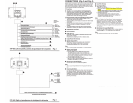
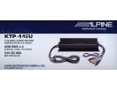
CONNECTION CHECKLIST (Fig. 7)
Please check your head unit for the conditions listed
below: (Fig. 7)
a.
The
head unit does not have a remote turn-on
or
power
antenna lead.
b.
The
head unit's power antenna lead is activated only when
the radio is on (turns off in the tape
or
CD Mode).
c.
The
head unit's power antenna lead is logic level output
(+)
5V, negative trigger (grounding type),
or
cannot sustain
(+) 12V when connected to other equipment in addition to
the vehicle's power antenna.
If any
of
the above conditions
exist, the remote turn-on lead of your KTP-445U must be
connected to a switched power source (ignition) in the
vehicle. Be sure to use a 3A fuse as close as possible
to
this ignition tap. Using this connection method, the KTP-
445U will turn on and stay on as long as the ignition switch
is on.
If this is objectionable, a SPST (Single Pole, Single Throw)
switch, in addition to the 3A fuse mentioned above, may be
installed in-line on the
KTP-445U turn-on lead. This switch will
then be used
to
turn on (and off) the KTP-445U. Therefore, the
switch should be mounted so that is accessible by the driver.
Make sure the switch is turned off when the vehicle is not
running. Otherwise, the amplifi
er
will remain on and drain the
battery.
(j)
Blue/White
~
Power Antenna
@ Remote Turn-On Lead
®
To
other Alpine components' Remote Turn-On Leads
@ SPST Switch (optional)
@ r=usa(3A) . _ . __
..
__ . ..
...
. .
(/)
As
close as possible to the vehicle's ignition tap
@ Ignition Source


Find Your Products By Category
Please Login
