
0
Owner's of the Alpine Car Stereo System Alpine Electronics Car Stereo System gave it a score of 0 out of 5. Here's how the scores stacked up:
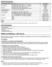


SPECIFICATIONS
Input
Sensitivity
Crossover
Dimensions
NOTE:
•
For product improvement, specifications and design are subject to change without notice.
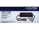
ACCESSORIES
•
Mounting Bracket ........................................................................................................................................................................... 2
• Self-
Tapping
Screw
(M4 x 12) ........................................................................................................................................................ 4
• Cable
Tie ........................................................................................................................................................................................ 2
• Input Wire Harness ........................................................................................................................................................................ 1
•
Output/Power Wire Harness .......................................................................................................................................................... 1
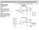
INSTALLATION
(Fig. 1
and
Fig. 2)
With this amplifier, there are two options for installation. Depending on which is best for your
tarQet
location, refer
to .instructions A or B
below.
~CAUTION
+
Caution on connection terminals/parts
•
Keep
electrically
conductive objects away from the unit's terminals/parts (power terminals, fuses, speaker
output terminals, RCA connectors, etc.). Doing so prevents a possible
short circuit and damage
to
the unit.
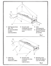
A.
Installation with mounting brackets
1.
Remove the two bottom screws on each end
panel.
2.
Use these screws to attach the
included
mounting brackets.
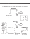
3.
Using the amplifier as a template, mark the four screw locations.
4.
Make sure there are no objects behind the surface that may become damaged during
drilling.
5.
Drill
the screw
holes.
6.
Position the KTP-445U over the screw holes, and secure with four self-tapping screws.
7.
Position the unit over the screw holes you prepared
earlier.
8.
Fasten the unit down with the four self-tapping screws (M4 x 12). Refer to Fig.
1.
B.
Installation with chassis mounting
loops
1.
Push each of the
included cable ties through the two mounting loops
near each end on the bottom panel.
2.
Use the cable ties to securely attach the amplifier
to
the vehicle's frame or chassis. Refer to
Fig.
2.
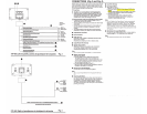
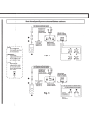
NOTE:
•
To
securely connect the ground lead, use an already installed screw on the metal
part
of
the vehicle
(marked*).
Be
sure this is a
good
ground by checking continuity to the battery (-) terminal.
As
much as possible
connect all equipment to the same ground point. These procedures will help eliminate noise.


Find Your Products By Category
Please Login
